Cell Specs
Cell Modules
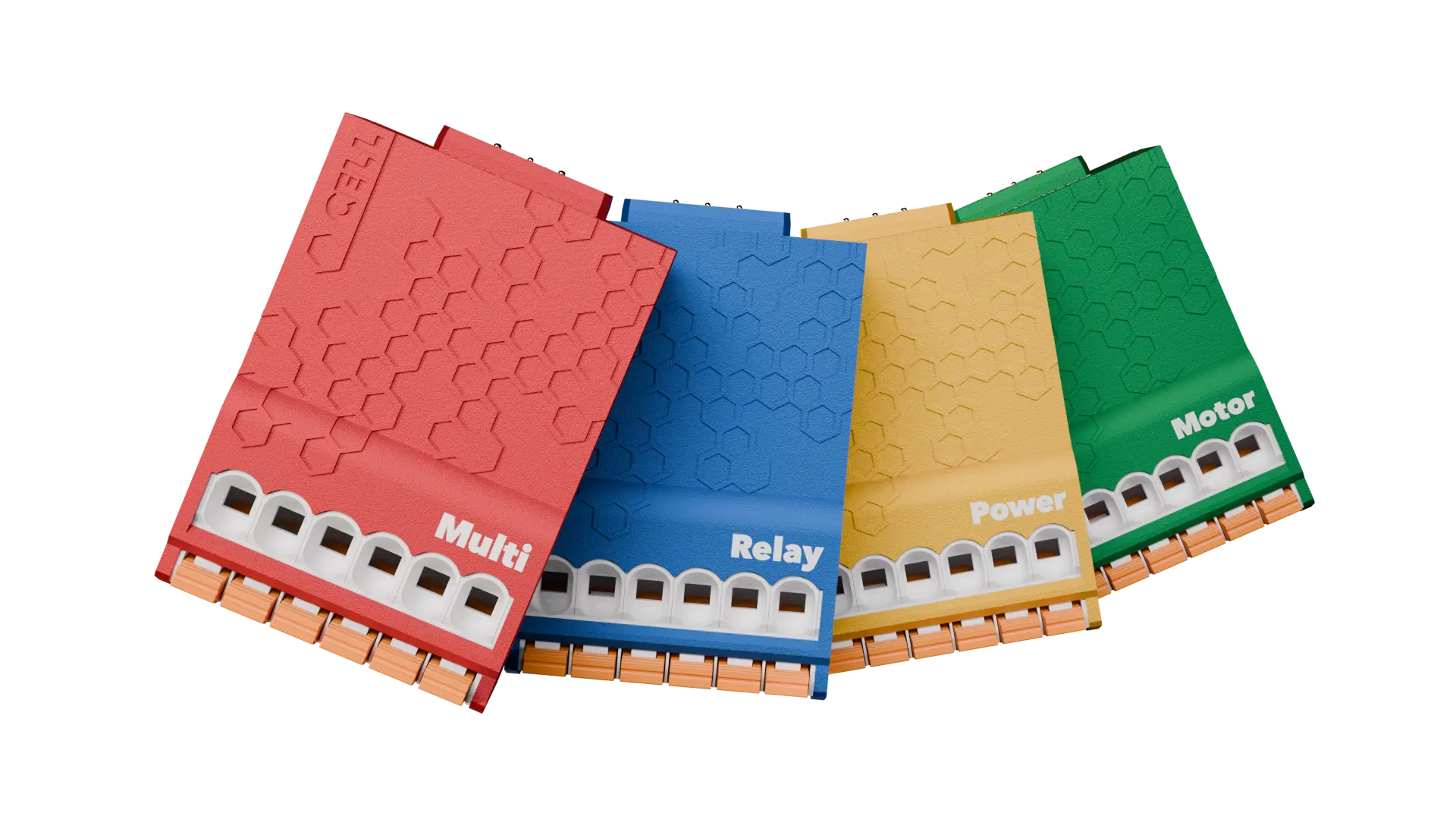
The PassiveLogic Cell modules are controllers that provides software-definable, universal I/O for thousands of use cases. It snaps into PassiveLogic Hive and Hive Mini controllers, replacing statically defined I/O with six terminals that can be configured for digital inputs and outputs or analog inputs and outputs.
Contacts
Type
6 universal software-defined terminals
Wire gauge
10–24 AWG
Stripping length
15–16 mm
Output per Terminal
Protocols
1-Wire
0–24VDC analog output
0–24VDC programmable, 40mA per channel
Supports 4–20mA, 0–10VDC, and powering devices up to 24VDC and 40mA
12VDC output
12VDC, 500mA per channel
AC output
24VAC, 500mA per channel
Ground
All terminals are software-defined and individually groundable
Input per Terminal
Voltage
0–24VAC, 0–24VDC
Continuously monitors voltage
Resistance
0–1MΩ, auto-ranging
Current
0–20mA
Mechanical
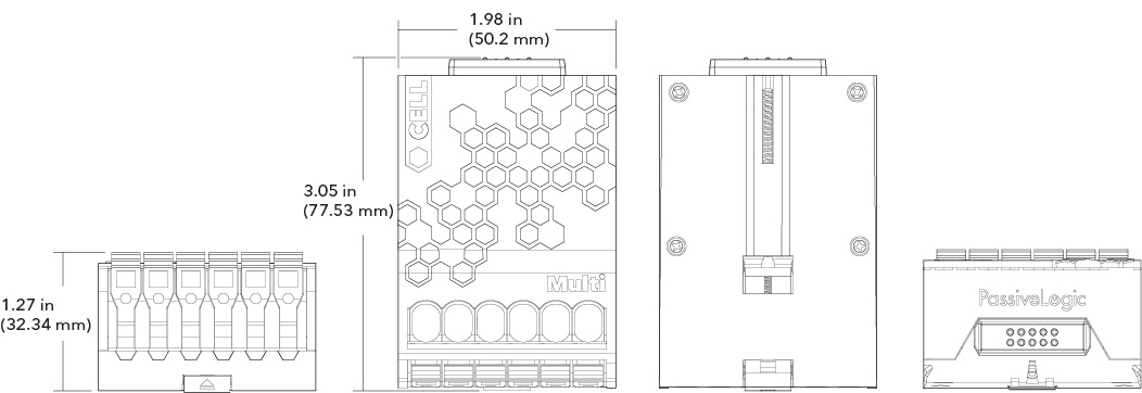
Height | Width | Depth
1.27 in (32.34 mm) | 1.98 in (50.20 mm) | 3.05 in (77.53 mm)
Weight
2.8 oz (80 g)
Inserting Cell Modules
Purpose
Cell I/O modules are where field wiring from sensors and controlled devices lands, allowing the Hive and Hive Mini to read inputs and drive outputs.
Insert module
Align the grooves along the base of the Cell with the guides on the bay, then push until it clicks into place.
Remove module
Firmly press the release button at the bottom center of the Cell to unlock it, then slide it out.
I/O Wiring
Lever-lock terminals
To add a wire, flip open the terminal lever, insert the appropriately stripped wire, then close the terminal lever.
Remove wire
To remove a wire, reverse the process.
LED status: Off
Empty. This terminal is not used in the current design.
LED status: White
Unverified. The expected wire connection is being verified. If this persists, check wiring.
LED status: Green
LED status: Green
Verified. The wiring on this terminal is fulfilled and functioning as expected.
LED status: Red
Error. Examples include over-voltage detected, device not connected, transient errors, or a previously verified connection no longer responding.
Wiring Examples
Analog input
4–20mA pressure sensor
Analog input
10k ohm thermistor
24VAC output
Power open/close/floating point actuator
Mechanical RTU control
RTU control wiring example using Multi Cell terminals
0–10VDC output
Modulating actuator control
Dimensions
Cell Specs
Cell Modules
The PassiveLogic Cell modules are controllers that provides software-definable, universal I/O for thousands of use cases. It snaps into PassiveLogic Hive and Hive Mini controllers, replacing statically defined I/O with six terminals that can be configured for digital inputs and outputs or analog inputs and outputs.
Contacts
Type
6 universal software-defined terminals
Wire gauge
10–24 AWG
Stripping length
15–16 mm
Output per Terminal
Protocols
1-Wire
0–24VDC analog output
0–24VDC programmable, 40mA per channel
Supports 4–20mA, 0–10VDC, and powering devices up to 24VDC and 40mA
12VDC output
12VDC, 500mA per channel
AC output
24VAC, 500mA per channel
Ground
All terminals are software-defined and individually groundable
Input per Terminal
Voltage
0–24VAC, 0–24VDC
Continuously monitors voltage
Resistance
0–1MΩ, auto-ranging
Current
0–20mA
Mechanical
Height | Width | Depth
1.27 in (32.34 mm) | 1.98 in (50.20 mm) | 3.05 in (77.53 mm)
Weight
2.8 oz (80 g)
Inserting Cell Modules
Purpose
Cell I/O modules are where field wiring from sensors and controlled devices lands, allowing the Hive and Hive Mini to read inputs and drive outputs.
Insert module
Align the grooves along the base of the Cell with the guides on the bay, then push until it clicks into place.
Remove module
Firmly press the release button at the bottom center of the Cell to unlock it, then slide it out.
I/O Wiring
Lever-lock terminals
To add a wire, flip open the terminal lever, insert the appropriately stripped wire, then close the terminal lever.
Remove wire
To remove a wire, reverse the process.
LED status: Off
Empty. This terminal is not used in the current design.
LED status: White
Unverified. The expected wire connection is being verified. If this persists, check wiring.
LED status: Green
LED status: Green
Verified. The wiring on this terminal is fulfilled and functioning as expected.
LED status: Red
Error. Examples include over-voltage detected, device not connected, transient errors, or a previously verified connection no longer responding.
Wiring Examples
Analog input
4–20mA pressure sensor
Analog input
10k ohm thermistor
24VAC output
Power open/close/floating point actuator
Mechanical RTU control
RTU control wiring example using Multi Cell terminals
0–10VDC output
Modulating actuator control
Dimensions